XY Translator Development
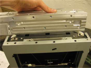
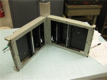
Left: the laboriously machined Aluminum bracket that joins the two scanner bodies. Right: the joined scanners.
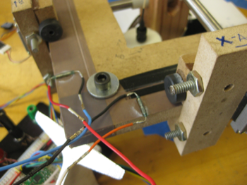
My first XY translator design attempted to employ two identical salvaged scanners to drive the two axes. The two scanners were bolted to a precision-machined Aluminum bracket. I had suspected that it would be easier to center my design around the high-precision scanner positions than to attempt to build an entire positioning system from scratch. The design I settled on was risky in that it drove each axis from only one end and relied on near-zero friction on the un-driven end. I hoped to achieve this low-friction by using high-precision roto-linear bearings that had been commercially manufactured. Unfortunately, these roto-linear bearings (seen above mounted in Aluminum blocks in the first image) did not provide reliable low friction, which rendered the prototype inoperable.
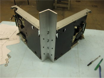
Left: detail of the bolting to the bracket. Right: the prototype translation system.
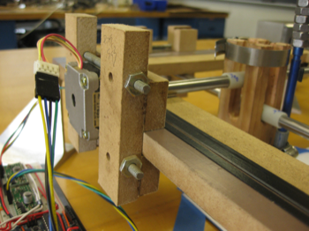
I next discovered the clever cable-based linear translation system implemented by Ilan Moyer in his FoamCore CNC Project. It took just a day and a half of fiddling in the machine shop to create a functional prototype. I employed 1/2" MDF as my primary structural material because of its high tolerances and the ease with which it can be worked with simple tools. I cut the square frame and the motor mounting blocks on a table saw and used a vertical mill to remove material inside the frame. I assembled the motor mounts with super glue and threaded rod and lined the perimeter of the frame with Teflon tape to reduce friction from the riding motor mounts.
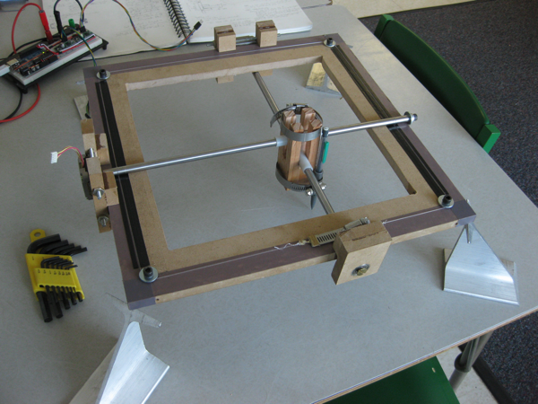
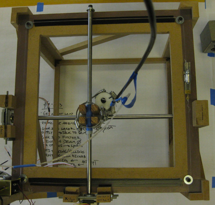
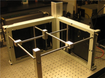
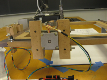
Left: the new translation system during early testing. Right: the translation system in use with the laser print head.
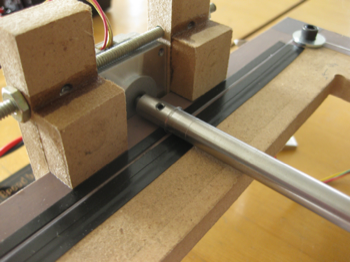
I used reamed nylon bushings to create primitive, but very effective roto-linear "bearings" for the simple translation head. The bushings ride on 1/2" drill rod that is driven on one end by a stepper motor. I reamed the end of each gentry shaft to the diameter of the stepper motor shafts and added a threaded hole to secure the motor shaft with a set screw. Because the wrapped, tensioned cables (high strength fishing line) prevent linear translation in the plane of the frame, the torque from the motor results in rotary motion of the shaft, which causes it to roll. The gantry rod that rides on the underside of the frame required a bearing block to support its free hanging end and prevent it from falling out of plane with the frame.
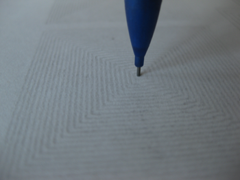
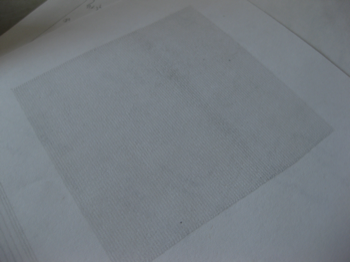
I tested the positioning accuracy of my new translation system with simple calibration patterns.
Details of the assembly of the motor mounts. Super glue and threaded rod hold the simple strips of MDF in place.
The motor mounts were simple 1 inch-wide strips of MDF cut on a table saw. The mounts were assembled and fit to the motors in place, after the motors had been secured to the gantry shafts. This allowed for a close fit and reduced construction time by doing away with the need for precise measuring. Each mount has two lower contact pads an two upper contact pads, each secured to verticals. I first drilled the two verticals to pass through the two pieces of drill rod that clamp the mount to the motor. Once the verticals were secured to the motor, I attached one upper contact pad to its vertical, pressing it flush against the Teflon-taped frame. Once it was secured, I clamped the mount to the frame and secured the other upper pad flush to the frame. I attached the tow lower pads with 0.010" shim stock separating the contact surfaces from the Teflon-coated frame to allow some room for expansion of the MDF in humidity.
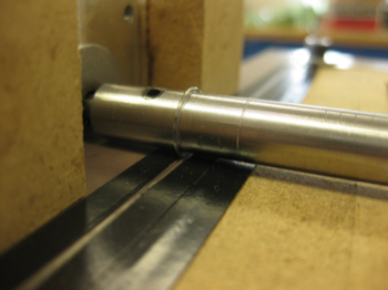
Left: Teflon tape (purple) lowers the friction between the motor mount and the frame. Right: layers of electrical tape guide the cable, preventing small lateral forces from walking the cable along the shaft.
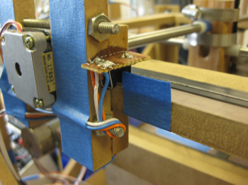
Left: simple magnetic end-stops. Right: more accurate and reliable optical end-stops.
I experimented with magnetic end-stops by using cheap ceramic magnets and reed switches. Though reliable for from a safety standpoint (the reed switches always triggered when th magnet was close), they were not useful for calibration. The "sticktion" between the contacts within the capsule of the reed switch did not disengage predictably, which made homing operations impossible. I elected to use optics end-stops because of their precision and consistent sensing.
blog comments powered by Disqus